4x4 and off road forum inside relay 4 pin wiring diagram image size 640 x 480 px and to view image details please click the image.
Mini relay 4 pin micro relay wiring diagram.
Here we look at relay switch pin diagram and the different kinds of relay switches.
The iso defines this type of relay as 1 inch 2 5 cm by 1 inch 2 5 cm by 0 5 inches 25 4 mm by 25 4 mm by 12 7 mm.
Determine that the relay is an iso micro type.
The automotive iso mini relays we have been looking at above are typically available in two types of pin layout designated type a and type b layouts.
A open your fuse box and try see if there is any unused 4 pin mini or 4 pin micro relay sockets.
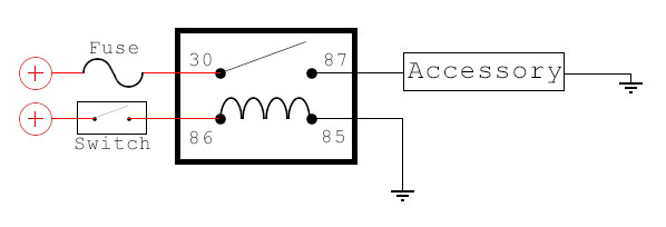
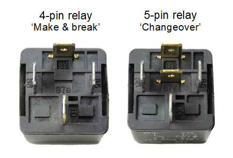
4 pin relay 4 pin relays use 2 pins 85 86 to control the coil and 2 pins 30 87 which switch power on a single circuit.
The difference between a 4 and 5 pin relay is that a 4 pin relay is used to control a single circuit whereas a 5 pin relay switches power between two circuits.
These layouts are shown on the two 5 pin relays below pin 87a not present on 4 pin relays.
I have attached the electrical wiring diagram from the turn indicator i believe what you will discover is that the turn signal and hazard the 8 pin flasher relay toyota is using here is kinda alien to me.
87 and 87a are the two contacts to which 30 will connect.
When a relay contact is closed there is a closed contact when the relay is not energized.
Relay diagrams pirate4x4.
Look for a relay diagram or a relay schematic that is printed on the side of the relay to determine.
Mini relay wireless switch 12v 433mhz remote control relay switch secure 1 channel micro receiver with transmitter system in latched mode dc 3 7v 5v 6v 7v 9v 12v 4 1 out of 5 stars 109 10 99 10.
Protection diode and spike suppression resistor for automotive relays.
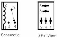
Note that each pin is numbered.
85 and 86 are the coil pins while 30 87 and 87a are the contact pins.
Relays switches are used to open and close circuits electromechanically or electronically.
Here is a picture gallery about relay 4 pin wiring diagram complete with the description of the image please find the image you need.
In a diode protected relay mini relays must be pin 85 power pin 86 ground micro relays must be pin 2 power pin 1 ground.
Numbers of a relay.
Looking at the diagram we see the pinout of a typical 12v relay.
If the coil is not activated 30 will always be connected to 87a.


